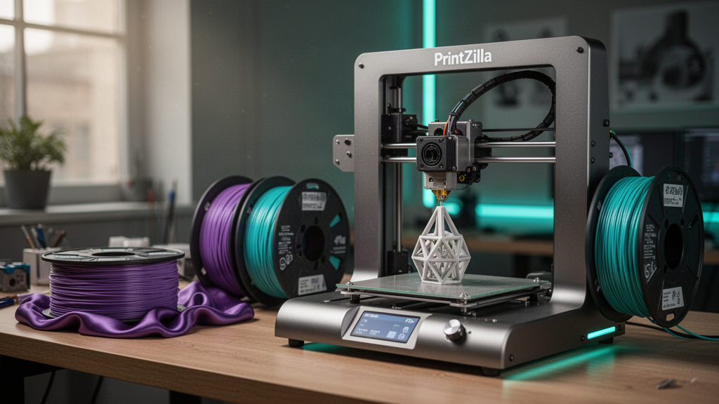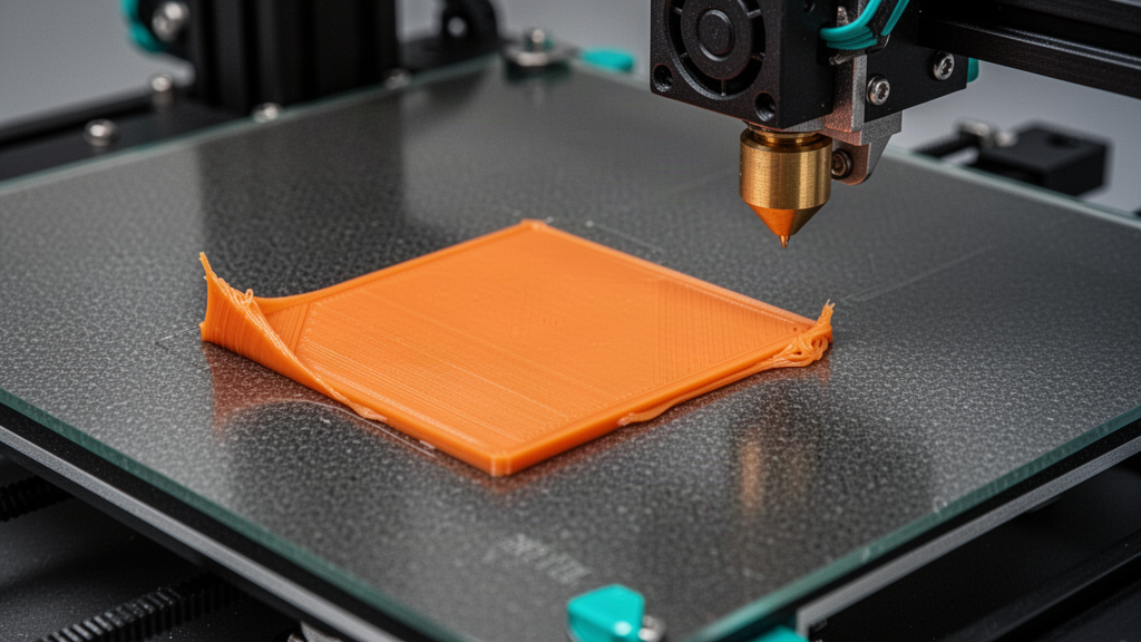
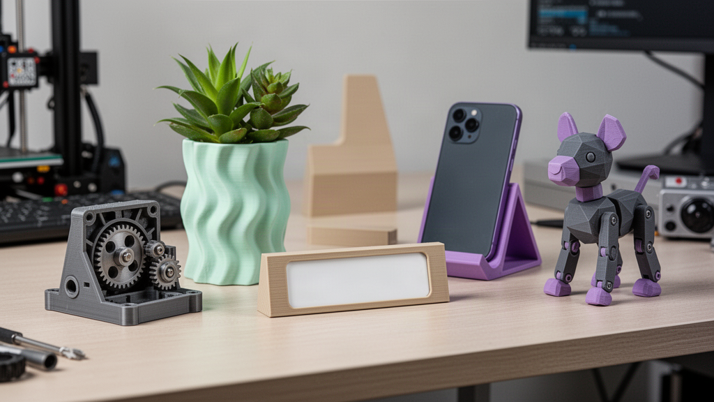
What you need to know.
A broken clip, obsolete knob or mystery bracket doesn't always need to end up in the bin. Learn the real workflow from photographs to measured, tested replacement.
- A photograph can guide a replacement design but usually cannot establish the exact dimensions, hidden holes or tolerances.
- A ruler or caliper measurement, several angles and the original part are often more valuable than a dramatic single photo.
- Replacement parts need the right material, print orientation and real-world test; do not casually replicate safety-critical components.
- PrintZilla's Photo Lab and print enquiry tools help explore a design, with human review before any promised physical production.
Can a broken part really be 3D printed from photographs?
Yes, some straightforward non-safety-critical plastic parts can be reconstructed from photographs, but a photo alone is rarely a dimensionally accurate manufacturing plan.
Think of a drawer pull, cable-routing bracket, cap, missing toy accessory or decorative appliance trim. If the original has a simple shape and accessible mounting features, rebuilding it as a 3D model may be feasible. The image tells a designer what an object looks like. Measurements and real-world checks tell them whether the replacement will actually fit. That difference is the heart of responsible reverse engineering.
There are two broad approaches. For a simple object, take measurements and use CAD sketches to build a new model. For a highly irregular sculptural object, 3D scanning or multi-image reconstruction may provide a starting mesh, but the result often still needs repair, scaling and redesign. The final output must be checked for strength and intended use, not merely rendered beautifully.
Which photographs should you take for a 3D replacement part?
- Take one image straight-on from the front, with the part lying flat and in focus.
- Take matching side, back and top views; hidden clips and screw holes are as important as the visible face.
- Add a familiar scale reference and a ruler, but also record the real dimensions separately. Perspective can distort photographed measurements.
- Photograph the broken edges and where the part attaches so the designer can understand the load and direction of force.
- Include one photograph of the surrounding assembly or an intact matching part, without revealing sensitive personal details.
- Use soft even lighting and a plain background rather than a reflection-heavy workbench.
Avoid extreme wide-angle phone shots very close to the subject. They make edges appear curved and distances unequal. Move back slightly and zoom or crop where sensible. Do not edit out important cracks; a design reviewer needs to know which part failed and why. If the original part is lost, photograph the opening, thread, mating component or neighbouring identical feature. Those often matter more than guesses about the missing object.
The five measurements that make or break the fit
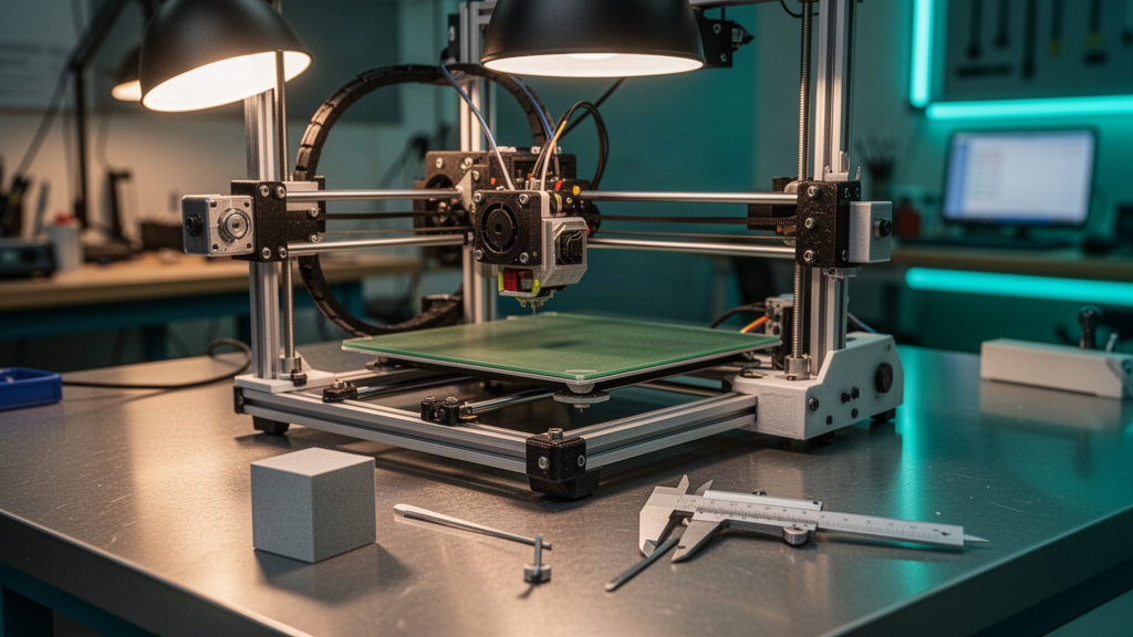
A replacement part may look identical in a preview yet fail because a hole is half a millimetre out of position. Record the overall length, width and thickness, the distance between mounting holes, critical clip or tab thickness, and the dimensions of any mating surface. Include hole diameters and whether a clearance or interference fit is needed. Where you can, measure the intact mounting location as well as the broken piece.
Use a caliper if you have one. Note whether each figure is a direct measurement or an estimate from the photo. For holes that will accept screws, do not assume the nearest printed thread will be durable. A designer may need to specify an insert, clearance hole or fastener. Thermal expansion, shrinkage, flexible clips and printed-layer orientation can all alter the resulting fit.
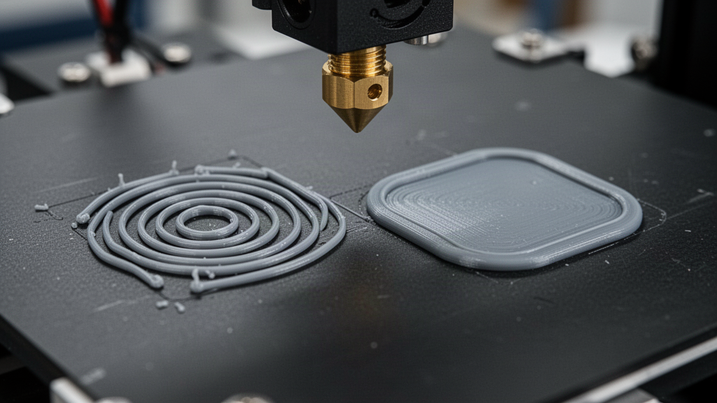
Does AI automatically turn one photograph into a printable STL?
Treat an image-to-3D result as a starting hypothesis. AI and photogrammetry can help propose visible surfaces; they cannot reliably invent unseen mounting hooks or prove precise internal geometry from a single viewpoint. Autodesk describes the use of a reference image as a canvas that can be calibrated in Fusion, so a designer can trace and dimension an appropriate shape. That is a manual modelling workflow, not a guarantee of one-click precision.
In a professional workflow, the designer rebuilds functional geometry as editable CAD features, checks tolerances, then exports a printable model. For an organic sculptural piece, a scan mesh may be repaired and converted where appropriate. Keep the original measurements alongside the digital file. It is far easier to correct a failed clip when its intended dimensions are recorded than to modify an opaque mesh by eye.
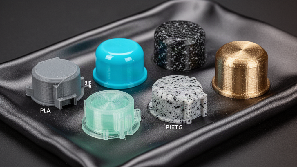
Which 3D printing material suits a replacement plastic part?
| Situation | Material direction | Practical caution |
|---|---|---|
| Decorative knob or trim | PLA can suit low-stress indoor use | Heat and repeated force may be limitations |
| Everyday bracket or cover | PETG is worth considering | Check stiffness, warping and part orientation |
| Flexible protective insert | TPU may suit elastic deformation | Dimensions and hardness grade still matter |
| Hot, outdoor or loaded component | Professional material review required | Temperature, UV, creep and safety validation may rule out desktop FDM |
A higher print resolution cannot compensate for the wrong material. Parts near hot motors, electrical connections, direct sunlight or repeatedly loaded hinges need additional scrutiny. Printed plastics are often anisotropic: they may be much weaker across layer bonds than along a continuous bead. A clip that works in one orientation might break immediately when turned through ninety degrees.
Which replacement parts should not be casually 3D printed?
Avoid treating the printer as a shortcut for safety-critical repairs. Vehicle braking, steering, seatbelt and structural parts; electrical mains enclosures; gas or water pressure fittings; medical equipment; child safety products and fire-control components require appropriate certification, engineering assessment or manufacturer-approved replacements. Some must not be reproduced through an ordinary consumer print workflow at all.
Even an apparently simple part can fail in a dangerous way if it retains a load, holds a heater, seals liquid or restrains another component. If you do not know its operating temperature, force or regulatory obligations, use a certified replacement or consult a competent specialist. This guide is about everyday non-critical plastic parts, not a sign-off for regulated applications.
How to prototype, test-fit and iterate safely
- Review the measured CAD model and flag dimensions that were estimated from photographs.
- Slice a small test coupon or the critical mounting section before printing the full part.
- Use appropriate material and orientation, and inspect the first layer before continuing.
- Check the fit at rest without excessive force; look for cracks, poorly fused layers or sharp edges.
- Record corrections as dimensions, update the CAD file, and repeat the test before any full production run.
A measured, iterative prototype can be more useful than a photorealistic image. Ask what the part does, which faces must be accurate, whether it flexes and which old failure caused the break. Photographs, measurements and the reason for replacement should remain available to the reviewer. If there are no reliable measurements, label the model exploratory rather than production ready.
How PrintZilla approaches a photo-to-part enquiry
PrintZilla separates exploration from manufacturing. You can try reference-image concepts in Photo Lab, understand replacement design in Parts, and submit a model for human print review through Printworks. The broader app also contains design and inspection tools, but an attractive virtual preview is not proof that a part will work. A quote, production plan and physical job need confirmation.
Start with a clear explanation: what the part is, what broke, its exact use, any known dimensions and whether you have the original. Include enough photographs to show the mounting mechanism. State clearly if the part touches heat, electricity, children, food or significant loads. Where a suitable non-critical part can be modelled, agree on material, finish and acceptance criteria before proceeding.
Frequently asked questions
01Can you make an accurate 3D print from one photo?
A single image can help describe a shape, but it usually cannot reveal hidden features or precise dimensions. For a reliable fit, supply measurements, multiple views and ideally the original mating component.
02What if the original plastic part is missing?
Measure and photograph the component it attaches to. An intact identical feature, mounting hole or manufacturer drawing can provide more useful information than guessing the missing piece's shape.
03Will a printed replacement be as strong as the original?
Not necessarily. Material, geometry, wall direction, temperature and print process matter. Safety-critical and regulated replacement parts require appropriate engineering and certified alternatives.
04Does PrintZilla's Photo Lab automatically send an item to a real printer?
No. It is an exploratory design workflow. A physical part requires review, agreement on materials and dimensions, and a confirmed production request.
Sources and useful references
We link to official documentation and publisher guidance where useful. Advice and platform features can change; verify current details with the original source, your printer maker and relevant service provider.
Found a broken part worth saving?
Start with photos and dimensions in Photo Lab, then request a reviewed print plan for suitable non-critical replacement parts.
Explore Photo-to-Part Studio